All Microchip micro-controllers, from PIC10F to PIC32F, has Timer 0 module. Few years back the Timer 0 module only support 8-bit timer but later in some part Microchip enhanced the Timer 0 module to include the 16-bit timer.
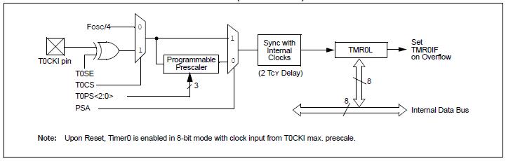

The block diagram on top is the 8-bit Timer 0 module and bottom is the 16-bit Timer 0 module. Referring to the block diagram, both the front end blocks are the same except the timer registers, TMR0L and TMR0H (TMR0 High Byte).
If Timer 0 module is configured as 8-bit timer (set T08BIT bit in T0CON register), only TMR0L register is used. Else, if configured as 16-bit timer (clear T08BIT bit in T0CON register), TMR0L and TMR0H register are used. TMR0H is actually a high byte of TMR0L which is not directly readable or writable, any write/read on/from TMR0H has no effect. In order to read the 16-bit timer, one just need to read the TMR0L register. Likewise, any write to TMR0L register will also write TMR0H in 16-bit timer mode.
Moving from left to right of the block diagram, the input clock can be either from T0CKI pin or internal instruction clock cycle (Fosc/4) where Fosc is the micro-controller operating clock. If the clock input from T0CKI pin, one needs to define the timer count increment on high-to-low or high-to-low transition of the clock at T0CKI pin. It can be set via PSA bit in the T0CON register.
The Prescaler is programmable where it is used to slow down the clock count, basically. The 3-bit Prescaler is used to select which prescaler to use with the timer. It ranges from 1:256 to 1:2. What does this mean? If you set the Prescaler to 1:2 meaning every 2 clock transition it only counts as 1 count.
How do you calculate the timer period with Prescaler?
For example, operating clock is 4 MHz (Fosc) and Prescaler is set to 1:32.
Instruction clock cycle = Fosc/4 = 4 MHz/4 = 1 MHz
After Prescaler = 1 MHz / 32 = 31.25 kHz, or 1 tick = 32 uSec
One can monitor the Timer 0 interrupt flag bit in order to determine timer set has expired or overflow.
How do you set the Timer 0 to overflow every 1 mSec?
From the example above, 1 tick is 32 uSec.
For 1 mSec, number of ticks = 1 mSec / 32 uSec = 31.25 tick ~ 31 ticks
Set Timer 0 to 31 ticks to overflow = 256 ticks - 31 ticks = 225 ticks (8-bit timer mode)
After setting TMR0L to 225, it will counts from 225 to 256 and roll over to 0. Rolling over will assert the TMR0 interrupt flag bit. One can monitor the TMR0 interrupt flag bit to determine the time expire or overflow.
NOTE: Please make sure to clear the TMR0 interrupt flag bit else it keeps going into the interrupt service routine and if polling method is used it will directly skip the code.
For 16-bit mode, the maximum number of ticks is 65536 instead.
Set Timer 0 to 31 ticks to overflow = 65536 ticks - 31 ticks = 65505 ticks (16-bit timer mode)
Please bear in mind some Microchip micro-controllers do have TMR0 on/off bit so need to remember to turn on the Timer 0 module else it won't work. I hope I cover most of the Timer 0 module function. If you have any question, please drop me an email.

No comments:
Post a Comment